Solicitud
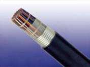
The cables are designed for use as subscriber distribution cables and as connection between central offices. The cables are suitable for installation in ducts and aerial installation with integral suspension strand. A figure-8 self support option is offered for aerial installation.
Normas

• ICEA S-85-625(formerly RUS (REA) PE-22 & RUS (REA) PE-38)
Construcción
Conductores
Solid annealed bare copper, 0.4/0.5/0.63/0.9mm, as per ASTM B-3/class 1 of IEC 60228
Aislamiento
Solid polyethylene as per ASTM D 1248/IEC 60708
Pares trenzados
Insulated conductors are twisted into pairs with varying lay length to minimize crosstalk
Elemento de cableado
Twisted Pairs
Cable Troncal Asamblea
Cables of 25 pairs or less are assembled into cylindrical core. Cables larger than 25 pairs are assembled into units, which are then used to form the core. Units are identified by colour coded binders
Envasado básico
One or more non-hygroscopic polyester tapes are helically or longitudinally laid with an overlap. These tapes furnish thermal, mechanical as well as high dielectric protection between shielding and individual conductors
Moisture Barrier
A layer of corrugated copolymer coated aluminium tape (0.2mm/8mil) is applied longitudinally with overlap over the cable core to provide 100% electrical shielding coverage and ensures a barrier against water vapor
Vaina
Black Low density or medium density polyethylene as per ASTM D 1248/IEC 60708, being able to withstand exposure to sunlight, temperature variations, ground chemicals and other environmental contaminants
Ripcord
Ripcord may be provided for slitting the sheath longitudinally to facilitate its removal
Pares de repuesto (optional)
Spare pairs may be provided for large pair cables
Continuidad Wire(optional)
One tinned copper drain wire may be longitudinally laid to ensure electrical continuity of the screen
Facultativo Construcción
Libre-Cables de apoyo
A 7-strand galvanized steel strand is used as support wire. Black polyethylene sheath covers both core and support wire in a figure-8 construction
Propiedades eléctricas
Nominal Conductor Diameter |
mm |
0.4 |
0.5 |
0.63 |
0.9 |
Conductor Gauge Size |
AWG |
26 |
24 |
22 |
19 |
Maximum Average DC Resistance |
Ω/km / Ω/mile |
140/225 |
87/140 |
55/88.6 |
27.0/43.4 |
Maximum Individual DC Resistance |
Ω/km / Ω/mile |
144.2/232 |
89.5/144 |
56.5/91.0 |
28.0/45.0 |
Minimum Insulation Resistance @500V DC |
MΩ.km / MΩ.mile |
1600/1000 |
1600/1000 |
1600/1000 |
1600/1000 |
Maximum Average Resistance Unbalance |
% |
1.5 |
1.5 |
1.5 |
1.5 |
Maximum Individual Resistance Unbalance |
% |
5 |
5 |
5 |
5 |
| Average Mutual Capacitance |
nF/km / nF/kft |
48.5-54.0
/14.8-16.5 |
48.5-54.0
/14.8-16.5 |
48.5-54.0
/14.8-16.5 |
48.5-54.0
/14.8-16.5 |
| Maximum Individual Mutual Capacitance |
nF/km / nF/kft |
57/17.4 |
57/17.4 |
57/17.4 |
57/17.4 |
| Maximum Individual Capacitance Unbalance pair-to-pair |
pF/km / pF/kft |
145/44 |
145/44 |
145/44 |
145/44 |
| Capacitance Unbalance RMS pair-to-pair |
pF/km / pF/kft |
45/13.7 |
45/13.7 |
45/13.7 |
45/13.7 |
| Maximum Individual Capacitance Unbalance pair-to-ground |
pF/km / pF/kft |
2625/800 |
2625/800 |
2625/800 |
2625/800 |
| Maximum Average Capacitance Unbalance pair-to-ground |
pF/km / pF/kft |
574/175 |
574/175 |
574/175 |
574/175 |
| Maximum Conductor Loop Resistance @20°C |
Ω/km / Ω/mile |
300/482 |
192/309 |
114/183.6 |
60/96.4 |
| Impedance @1KHz |
Ω |
994 |
796 |
660 |
445 |
| Impedance @100KHz |
Ω |
147 |
134 |
125 |
122 |
| Impedance @512KHz |
Ω |
120 |
118 |
117 |
116 |
| Impedance @1MHz |
Ω |
117 |
115 |
114 |
113 |
| Maximum Average Attenuation @0.8KHz |
dB/km / dB/kft |
1.64/0.5 |
1.30/0.39 |
1.04/0.32 |
0.74/0.22 |
| Maximum Average Attenuation @1KHz |
dB/km / dB/kft |
1.68/0.51 |
1.35/0.41 |
1.08/0.33 |
0.76/0.23 |
| Maximum Average Attenuation @3KHz |
dB/km / dB/kft |
3.18/0.97 |
2.52/0.77 |
2.01/0.61 |
1.42/0.43 |
| Maximum Average Attenuation @150KHz |
dB/km / dB/kft |
11.4/3.47 |
8.3/2.53 |
6.2/1.89 |
4.4/1.34 |
| Maximum Average Attenuation @772KHz |
dB/km / dB/kft |
24.3/7.4 |
19.4/5.9 |
15.4/4.7 |
10.8/3.3 |
| Maximum Average Attenuation @1000KHz |
dB/km / dB/kft |
27.1/8.25 |
21.4/6.52 |
17.5/5.33 |
12.8/3.89 |
| Dielectric Strength |
|
|
|
|
|
| Conductor to Conductor (3secs) |
V DC |
2400 |
3000 |
4000 |
5000 |
| Conductor to Screen (3secs) |
V DC |
10000 |
10000 |
10000 |
10000 |
| Minimum EL Far-end Cross-talk-Mean Power Sum |
|
|
|
|
|
@150KHz |
dB/305m / dB/kft |
61 |
63 |
63 |
65 |
@772KHz |
dB/305m / dB/kft |
47 |
49 |
49 |
57 |
@1.6MHz |
dB/305m / dB/kft |
41 |
42 |
43 |
44 |
@3.15MHz |
dB/305m / dB/kft |
35 |
37 |
37 |
39 |
@6.3MHz |
dB/305m / dB/kft |
29 |
31 |
31 |
33 |
| Minimum Far-end Cross-talk-Worst Pair Power Sum |
|
|
|
|
|
@150KHz |
dB/305m / dB/kft |
57 |
57 |
57 |
59 |
@772KHz |
dB/305m / dB/kft |
43 |
43 |
43 |
45 |
@1.6MHz |
dB/305m / dB/kft |
37 |
37 |
37 |
39 |
@3.15MHz |
dB/305m / dB/kft |
31 |
31 |
31 |
33 |
@6.3MHz |
dB/305m / dB/kft |
25 |
25 |
25 |
27 |
| Minimum Near-end Cross-talk-Mean Power Sum |
|
|
|
|
|
@150KHz |
dB/305m / dB/kft |
58 |
58 |
58 |
58 |
@772KHz |
dB/305m / dB/kft |
47 |
47 |
47 |
47 |
@1.6MHz |
dB/305m / dB/kft |
43 |
43 |
43 |
43 |
@3.15MHz |
dB/305m / dB/kft |
38 |
38 |
38 |
38 |
@6.3MHz |
dB/305m / dB/kft |
34 |
34 |
34 |
34 |
| Minimum Near-end Cross-talk-Worst Pair Power Sum |
|
|
|
|
|
@150KHz |
dB/305m / dB/kft |
53 |
53 |
53 |
53 |
@772KHz |
dB/305m / dB/kft |
42 |
42 |
42 |
42 |
@1.6MHz |
dB/305m / dB/kft |
38 |
38 |
38 |
38 |
@3.15MHz |
dB/305m / dB/kft |
33 |
33 |
33 |
33 |
@6.3MHz |
dB/305m / dB/kft |
29 |
29 |
29 |
29 |
Nominal Insulation Thickness |
mm |
0.15 |
0.2 |
0.26 |
0.3 |
Nominal Insulated Conductor Diameter |
mm |
0.7 |
0.9 |
1.15 |
1.5 |
1 2